For complicated geometries, you probably need some kind of a devoted CAD tool rather than a built-in Matlab functionality. GMSH is a nice open-source tool, and this is my weapon of choice for such problems.
Now, there is nothing specific about nested geometries in GMSH that should be reflected in the documentation. You might want to get familiar with basic GMSH functionalities of creating Points, Lines, Line Loops, Surfaces, Surface Loops, and Volumes. This can be done explicitly, via extrusions, and even spiced up with user-defined macros. Also, some additional functionality is available via OpenCASCADE geometry kernel enabled, but I'll skip it.
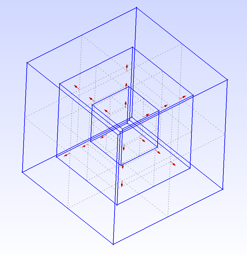
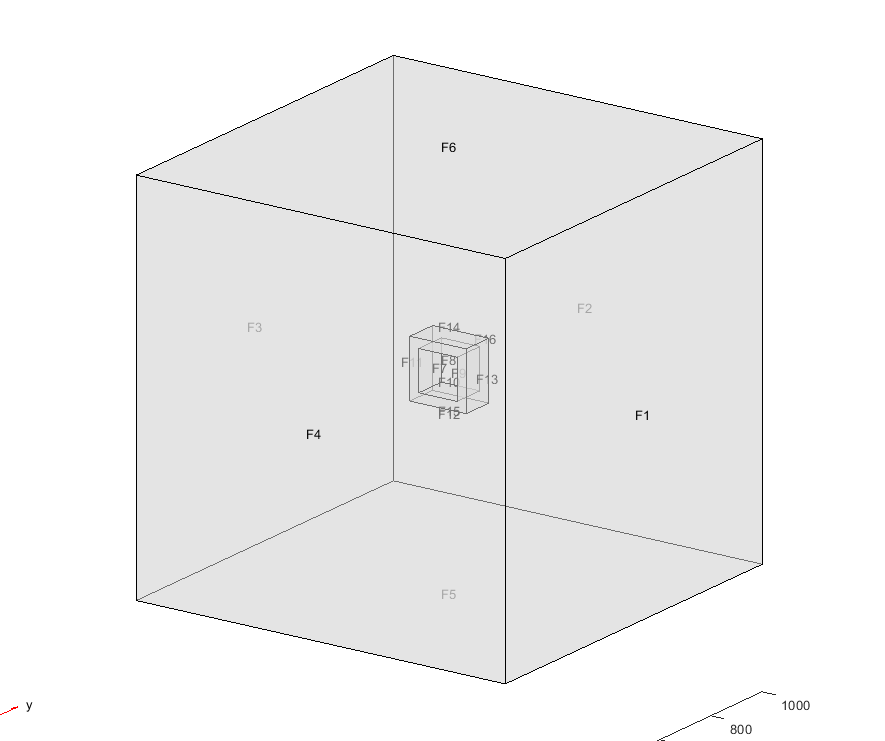
So, you want to draw 3 surfaces of the cube and create three volumes out of it with conformal tetrahedral elements. That's pretty much what your task boils down to.
I had a Macro that I tweked slightly already written, and I share it here with you. Take a look at how it works, but overall:
- there is a
Macro that draws a cube by subsequently creating the needed points, lines, line loops, surfaces and a surface loop given the center {x_cen,y_cen,z_cen} and a side length a
- the scrips calls this
Macro Cube three times with different side lengths a
- the
Macro returns the Surface Loop id into the array Elem_sl at the unit_element position, which is incremented in the main script
- in the end, three volumes are created:
Volume(1000) is a solid one corresponding to the most inner geometry, Volume(2000) is the middle one, that has Volume(1000) as its hole, and Volume(3000) is the outer one, that has Volume(2000) as its hole
- since the volumes use the same surfaces as their building blocks, the mesh is conformal between them
- if you also need the surface mesh and line mesh (say, to set up boundary conditions) you should add the needed entities in
Physical Surfaces and Physical Lines.
Macro Cube
    // Macro to draw an element surface, in this case, a cube
    // Input:
    //      unit_element                    - ID of the element in the overall structure
    //      x_cen, y_cen, z_cen             - location for the center of the cube
    //      a                               - cube side length
    //      cl                              - characteristic length for points
    // Output:
    //      Elem_sl[unit_element]           - surface loop for the unit element

    Elem_pts[0] = newp;     Point(Elem_pts[0])  = {x_cen+a/2,y_cen+a/2,z_cen+a/2,cl};
    Elem_pts[1] = newp;     Point(Elem_pts[1])  = {x_cen+a/2,y_cen-a/2,z_cen+a/2,cl};
    Elem_pts[2] = newp;     Point(Elem_pts[2])  = {x_cen-a/2,y_cen+a/2,z_cen+a/2,cl};
    Elem_pts[3] = newp;     Point(Elem_pts[3])  = {x_cen-a/2,y_cen-a/2,z_cen+a/2,cl};
    Elem_pts[4] = newp;     Point(Elem_pts[4])  = {x_cen+a/2,y_cen+a/2,z_cen-a/2,cl};
    Elem_pts[5] = newp;     Point(Elem_pts[5])  = {x_cen+a/2,y_cen-a/2,z_cen-a/2,cl};
    Elem_pts[6] = newp;     Point(Elem_pts[6])  = {x_cen-a/2,y_cen+a/2,z_cen-a/2,cl};
    Elem_pts[7] = newp;     Point(Elem_pts[7])  = {x_cen-a/2,y_cen-a/2,z_cen-a/2,cl};

    Elem_lns[0] = newl;     Line(Elem_lns[0])   = {Elem_pts[0],Elem_pts[2]};
    Elem_lns[1] = newl;     Line(Elem_lns[1])   = {Elem_pts[2],Elem_pts[3]};
    Elem_lns[2] = newl;     Line(Elem_lns[2])   = {Elem_pts[3],Elem_pts[1]};
    Elem_lns[3] = newl;     Line(Elem_lns[3])   = {Elem_pts[1],Elem_pts[0]};

    Elem_lns[4] = newl;     Line(Elem_lns[4])   = {Elem_pts[4],Elem_pts[6]};
    Elem_lns[5] = newl;     Line(Elem_lns[5])   = {Elem_pts[6],Elem_pts[7]};
    Elem_lns[6] = newl;     Line(Elem_lns[6])   = {Elem_pts[7],Elem_pts[5]};
    Elem_lns[7] = newl;     Line(Elem_lns[7])   = {Elem_pts[5],Elem_pts[4]};

    Elem_lns[8] = newl;     Line(Elem_lns[8])   = {Elem_pts[0],Elem_pts[4]};
    Elem_lns[9] = newl;     Line(Elem_lns[9])   = {Elem_pts[2],Elem_pts[6]};
    Elem_lns[10] = newl;    Line(Elem_lns[10])  = {Elem_pts[3],Elem_pts[7]};
    Elem_lns[11] = newl;    Line(Elem_lns[11])  = {Elem_pts[1],Elem_pts[5]};


    Elem_ll[0] = newreg;    Line Loop(Elem_ll[0]) = {Elem_lns[0],Elem_lns[1],Elem_lns[2],Elem_lns[3]};
    Elem_ll[1] = newreg;    Line Loop(Elem_ll[1]) = {Elem_lns[4],Elem_lns[5],Elem_lns[6],Elem_lns[7]};
    Elem_ll[2] = newreg;    Line Loop(Elem_ll[2]) = {Elem_lns[0],Elem_lns[9],-Elem_lns[4],-Elem_lns[8]};
    Elem_ll[3] = newreg;    Line Loop(Elem_ll[3]) = {-Elem_lns[1],Elem_lns[9],Elem_lns[5],-Elem_lns[10]};
    Elem_ll[4] = newreg;    Line Loop(Elem_ll[4]) = {-Elem_lns[7],Elem_lns[8],Elem_lns[3],-Elem_lns[11]};
    Elem_ll[5] = newreg;    Line Loop(Elem_ll[5]) = {-Elem_lns[6],Elem_lns[11],Elem_lns[2],-Elem_lns[10]};


    Elem_surf[0] = news;    Plane Surface(Elem_surf[0]) = {Elem_ll[0]};
    Elem_surf[1] = news;    Plane Surface(Elem_surf[1]) = {-Elem_ll[1]};
    Elem_surf[2] = news;    Plane Surface(Elem_surf[2]) = {-Elem_ll[2]};
    Elem_surf[3] = news;    Plane Surface(Elem_surf[3]) = {Elem_ll[3]};
    Elem_surf[4] = news;    Plane Surface(Elem_surf[4]) = {-Elem_ll[4]};
    Elem_surf[5] = news;    Plane Surface(Elem_surf[5]) = {-Elem_ll[5]};

    Elem_sl[unit_element] = newsl;
    Surface Loop(Elem_sl[unit_element]) = {Elem_surf[]};
Return

// MAIN SCRIPT
cl = 0.4;

x_cen = 0.;
y_cen = 0.;
z_cen = 0.;

unit_element = 0;

a = 1.;
Call Cube;
unit_element = unit_element+1;

a = 2.;
Call Cube;
unit_element = unit_element+1;

a = 3.;
Call Cube;
unit_element = unit_element+1;


Volume(1000) = {Elem_sl[0]};
Volume(2000) = {Elem_sl[1],Elem_sl[0]};
Volume(3000) = {Elem_sl[2],Elem_sl[1]};

Physical Volume(1) = {1000};
Physical Volume(2) = {2000};
Physical Volume(3) = {3000};
Remarks:
- could that be done with extrusions simpler? Yes.
- could that be done without a Macro? Sure.
- the goal was to use the existing script I have and show how to create these types of structures in GMSH relatively flexibly.


