I am using the mixed finite element method (MFEM) to solve the Poisson equation: $$\Delta h = 0,$$where $h$ denotes hydraulic pressure. The MFEM could determine the normal flux rate, $q_n$, through the interfaces between two adjacent grids, and the $q_n$ reads $$q_n=\frac{\partial h}{\partial n},$$ where $n$ is normal to the interface.
Here, I want to calculate the velocity $\mathbf{q}$, which is a vector, at a point inside one grid (triangle), after MFEM solution. So, my idea is $$\mathbf{q} = \sum_{i=1}^{3}Q_i\mathbf{W_i},\\ Q_i = q_{n,i}\cdot E_i,$$ where $Q_i$ is the total flux through the $i$th edge, $E_i$ is the edge length, and $\mathbf{W_i}$ is basis function that has the form: $$\mathbf{W_i} = \sigma_i\frac{E_i}{2A}(\mathbf{x}-\mathbf{P_i}),$$ where $\sigma_i$ is +1 or -1, and $\mathbf{P_i}$ is the vertices of the triangle. With barycentric coordinates, the $\mathbf{W_i}$ can be rewritten as $$\mathbf{W_i} = \sigma_i\frac{E_i}{2A}\left[\alpha(\mathbf{P_1-P_i}) + \beta(\mathbf{P_2-P_i}) + \gamma(\mathbf{P_3-P_i}) \right],$$ where $\alpha, \beta, \gamma$ are barycentric coordinates of a point inside the triangle.
In short, my inplementation of determining velovity $\mathbf{q}$ at a point is: (1) calculate the three basis functions, based on $\alpha, \beta, \gamma$; (2) calculate $Q_i$; and (3) determine $\mathbf{q}$. My matlab script is below.
clc;
close all;
clear all;

T = [0 0; 2 0; 0 2];
% triangle points: A, B, C

E = [norm(T(3, :) - T(2, :));
    norm(T(1, :) - T(3, :));
    norm(T(2, :) - T(1, :))]; % length of edges

A = det([T'; 1 1 1]) * 0.5; % area of trangle

patch('Vertices', T, 'Faces', [1 2 3], 'FaceVertexCData', zeros(size(T, 1), 1), 'FaceColor', 'interp', 'EdgeAlpha', 0.9, 'facealpha', 0); hold on
text(T(1, 1) .* 1.05, T(1, 2) .* 1.05, 'A', 'color', 'r'); hold on
text(T(2, 1) .* 1.05, T(2, 2) .* 1.05, 'B', 'color', 'r'); hold on
text(T(3, 1) .* 1.05, T(3, 2) .* 1.05, 'C', 'color', 'r'); hold on
hold on

Pnts_ = [0, 0.5
    0.3, 1.2
    0.9, 1.1];

for i = 1:size(Pnts_, 1)

    p_ = Pnts_(i, :); % point P in the triangle
    text(p_(1) .* 1.05, p_(2) .* 1.05, ['P', num2str(i)], 'color', 'b'); hold on
    scatter(p_(1), p_(2), 'o'); hold on

    % --------- calculate barycentric coordinates of P
    T_APC = [T(1, :); p_; T(3, :)];
    A_APC = det([T_APC'; 1 1 1]) * 0.5; % area of APC
    beta = A_APC / A;

    T_ABP = [T(1, :); T(2, :); p_];
    A_APB = det([T_ABP'; 1 1 1]) * 0.5; % area of ABP
    eta = A_APB / A;

    alpha = 1 - beta - eta;

    %---------- basis function of the T
    Phi = [];

    Phi(:, 1) = [E(1) / (2 * A) * (alpha * (T(1, 1) - T(1, 1)) + beta * (T(2, 1) - T(1, 1)) + eta * (T(3, 1) - T(1, 1)));
            E(1) / (2 * A) * (alpha * (T(1, 2) - T(1, 2)) + beta * (T(2, 2) - T(1, 2)) + eta * (T(3, 2) - T(1, 2)))];

    Phi(:, 2) = [E(2) / (2 * A) * (alpha * (T(1, 1) - T(2, 1)) + beta * (T(2, 1) - T(2, 1)) + eta * (T(3, 1) - T(2, 1)));
            E(1) / (2 * A) * (alpha * (T(1, 2) - T(2, 2)) + beta * (T(2, 2) - T(2, 2)) + eta * (T(3, 2) - T(2, 2)))];

    Phi(:, 3) = [E(3) / (2 * A) * (alpha * (T(1, 1) - T(3, 1)) + beta * (T(2, 1) - T(3, 1)) + eta * (T(3, 1) - T(3, 1)));
            E(1) / (2 * A) * (alpha * (T(1, 2) - T(3, 2)) + beta * (T(2, 2) - T(3, 2)) + eta * (T(3, 2) - T(3, 2)))];

    %----------- basis function multiply by flux through each edge
    Phi(:, 1) = Phi(:, 1) .* 1; % here, the flux though the edge BC is 1
    Phi(:, 2) = Phi(:, 2) .* -1; % here, the flux though the edge CA is -1
    Phi(:, 3) = Phi(:, 3) .* 0; % here, the flux though the edge AB is 0

    % ---------- velocity at point P
    velocity_p = [];
    velocity_p(1, 1) = sum(Phi(1, :));
    velocity_p(2, 1) = sum(Phi(2, :));
    disp(['velocity at P', num2str(i), ': [', num2str(velocity_p(1)), ', ', num2str(velocity_p(2)), ']'])
    quiver(p_(1), p_(2), velocity_p(1, 1), velocity_p(2, 1), 1); hold on
end

hold on
xlim([-0.5 2.5])
ylim([-0.5 2.5])
I just set the total fluxes through AC, BC and AB are -1, 1 and 0, respectively.
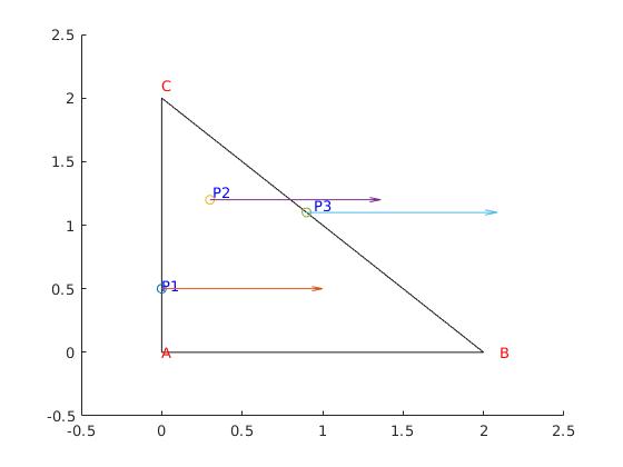
The result is
and I get
velocity at P1: [1, 0]
velocity at P2: [1.0621, 0]
velocity at P3: [1.1864, 0]
You can see the directions of velocities are all parallel to AB, which is what I expected. But, The problems are:
(1) the magnitudes of velocities (at P1 to P3) are different. I think that they should be equal everywhere, because I set ${Q_{AC}} = -1$, ${Q_{BC}} = +1$ and ${Q_{AB}} = 0$.
(2) also, the magnitudes are problematic. Since I defined the total flux through $AC$ is -1, the flux rate $\mathbf{q}$ should be like [1/2, 0].
What's wrong with my implementation?
