6
$\begingroup$

I am trying to create a simulation to help visualize how different chemical components flow through a network of pipes with associated valves, pumps, and chemical inputs. In this simulation, the pipes will be represented in 1D and the pump flow rates and valve states will ideally be able to be changed by the user during the simulation.

For example, the simplest pipe network might consist of three pipes and two pumps. The images below show what the simulation ideally would be able to do in real time. The arrows represent pumps, the circles represent inputs and outputs, and the lines represent pipes.
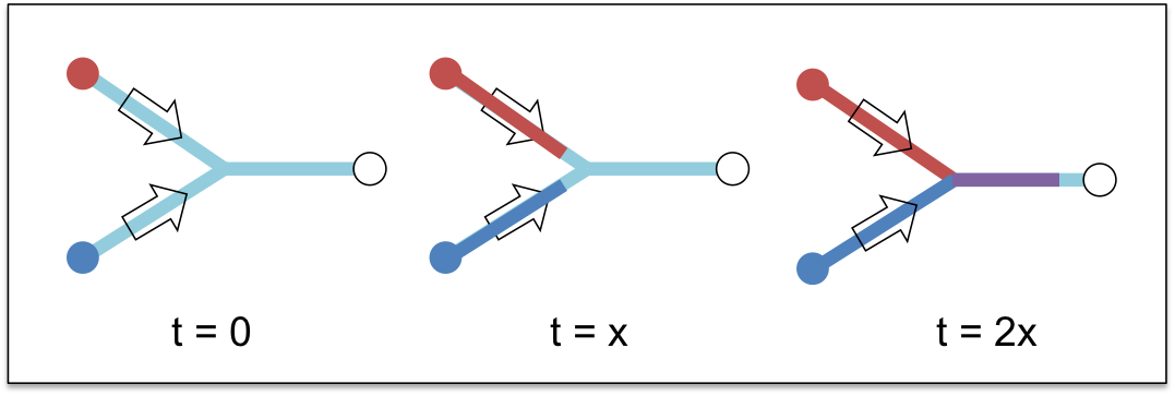
Simple pipe network example

I have already created a program that can take a representation of such a pipe network with pumps and valves in a given configuration and determine the flow rate in each pipe.

The difficulty I am having is in simulating the mass transport of the chemicals through the pipes. So far, I have tried an agent-based approach, where discrete boluses of fluid move through the pipes (one bolus for every v_pipe * dt meters in each pipe), and a simple finite difference scheme. The agent-based approach works in some situations, although doesn't work well when the flow rates of the pipes change. I have had some success with the finite difference method for a single pipe, but have problems with numerical diffusion and getting it to work well with a network of pipes.

Is there a good simulation method for implementing such a simulation of mass transport in a network of pipes where the flow rates in each pipe can vary? Would something like the finite volume method work?

$\endgroup$
1
  • 1
    $\begingroup$ Use a higher-order finite difference (or finite volume) method to reduce the diffusion. $\endgroup$ Commented Jan 29, 2014 at 6:31

2 Answers 2

4
$\begingroup$

This is actually a standard modeling problem if you consider the medium that flows through the network to be incompressible (e.g., liquids, or gases at low velocity). Then, you formulate everything in terms of fluxes (liters or kg per second) rather than in discrete parcels. The key realization is that the flux that goes into one end of the pipe equals the flux that comes out at the other. You then prescribe the flux at those inlets where you have a pump, and at all interior joints you have mass conservation, i.e., the sum of all fluxes into each node is zero. You will likely have to have one or more open outlets (such as the one on the right in your example) to make sure you don't have an overdetermined system. The variables you have are the fluxes $x_i$ through pipe $i$ for all of the pipes.

$\endgroup$
3
  • $\begingroup$ I have looked into such a network modeling technique, although to my understanding it would not allow me to keep track of the distribution of individual chemicals within each channel and therefore be able to provide a visual of the pipes filling up with different chemicals, as in my image. Is there a way for a flux-based approach be keep track, for example, that the first half of a pipe is filled with red dye, but the second half of the pipe is filled with blue dye? $\endgroup$
    – Will
    Commented Jan 29, 2014 at 5:50
  • $\begingroup$ Sure. In what I described above, each pipe just had a constant (non-time dependent) flux $x_i$ associated with it. This is still true if your pumping rates remain constant, but now you also need a (set of) concentrations at the outlet which may depend on time, say $c_i(t)$. If you know the volume $V_i$ of pipe i, then you know that it takes time $\tau_i=x_i/V_i$ for stuff to flow through the length of pipe $i$. Consequently, what flows out of pipe $i$ at time $t$, namely $c_i(t)$ is what flowed into it at time $t-\tau_i$. You again use the conservation properties to determine that. $\endgroup$ Commented Jan 29, 2014 at 13:06
  • $\begingroup$ In other words, you'll have something like $$c_i(t) = \frac{\sum_{j: \text{pipes merging into pipe}\ i} x_j c_j(t-\tau_i)}{\sum_{j: \text{pipes merging into pipe}\ i} x_j}$$. $\endgroup$ Commented Jan 29, 2014 at 13:08
1
$\begingroup$

It depends how realistic you want the simulation to be.

You could have a cellular automaton approach (maybe similar to your boluses approach). Where the automata behave as little agents moving in the fluid. Give each cellular automata simple rules like: 'at each time step move down this pipe at the pipes velocity', 'if you reach a node and it is closed stop', 'if the node is open move along both pipes', 'if speed increases/decreases lighten/darken colour by the fraction change in speed'.

Things get a little tricky at the junctions because you will want to apply rules which preserve mass as best as you can.

In principle each pipe could be it's own finite volume or finite difference simulation and connected together with appropriate boundary conditions. As you you only need advection (or maybe in the future diffusion?) finite volume is a good fit. As you noticed numerical diffusion becomes a problem here. To fix that I would move to a finite volume approach and apply a flux limiter like the MUSCL scheme.

$\endgroup$

Your Answer

By clicking “Post Your Answer”, you agree to our terms of service and acknowledge you have read our privacy policy.

Not the answer you're looking for? Browse other questions tagged or ask your own question.