5
$\begingroup$

Bathe's Finite Element Procedures shows the "nonlinear strain stiffness matrix" for a 2D truss element as $$ \frac {^tP} {L_0 + \Delta L} \left[ \begin{array}{ccc} 1 & 0 & -1 & 0 \\ 0 & 1 & 0 & -1 \\ -1 & 0 & 1 & 0 \\ 0 & -1 & 0 & 1 \\ \end{array} \right] $$

But other sources, such as this http://people.duke.edu/~hpgavin/cee421/truss-finite-def.pdf and the ANSYS theory manual, omit rows 1 and 3 (axial direction):

$$ \frac {^tP} {L_0} \left[ \begin{array}{ccc} 0 & 0 & 0 & 0 \\ 0 & 1 & 0 & -1 \\ 0 & 0 & 0 & 0 \\ 0 & -1 & 0 & 1 \\ \end{array} \right] $$

The extra 1's don't seem to be physically correct according to my intuition. They say the element becomes stiffer when it's under tension. That suggests the force/displacement relationship is not linear in a seemingly arbitrary way.

Bathe does say "Note that if the material stress-strain relationship is such that $^tP$ is constant with changes in $\Delta L$, [then something that seems to lead to the extra 1's being omitted]"

Perhaps it's using a generalization of Hooke's law which is nonlinear but doesn't have any extra parameters?

My experiments with nonlinear solid elements in Calculix show the same behavior as these truss elements with the extra 1's present.

EDIT: Using the full diagonal matrix with pre-stressed frequency analysis leads to what seems like an incorrect result - a 1D spring-mass system's natural frequency increases with tension on the spring. In other words, this common physics concept of gravity not influencing the motion described here is violated. https://share.ehs.uen.org/sites/default/files/Unit02Lesson2.pdf The same problem occurs with solid elements in Calculix. Are they really wrong?

EDIT 2: Example showing that the full-diagonal matrix does not work for pre-stressed frequency analysis. It's a 1D spring with length 1, spring constant k, mass m concentrated at each node and no constraints.
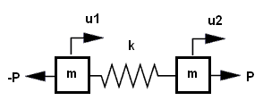
spring with 2 masses

The natural frequency should be independent of P. We can see this is true when using the 2nd geometric stiffness matrix above by solving the eigenvalue equation $$ (\textbf K_e + \textbf K_g - \omega^2 \textbf M) \textbf u = 0 $$ I form the 1D matrix by taking on the 1st and 3rd rows and columns from the 2D matrix above.

$ \textbf K_e = \left[ \begin{array}{rr} k & -k \\ -k & k \\ \end{array} \right] $ $ \textbf K_g = \left[ \begin{array}{rr} 0 & 0 \\ 0 & 0 \\ \end{array} \right] $ $ \textbf M = \left[ \begin{array}{rr} m & 0 \\ 0 & m \\ \end{array} \right] $

which has the non-zero eigenvalue $ \omega^2=\frac{2k}{m} $. This is consistent with a simple spring-mass oscillator. The factor of 2 appears because it's really two 1-dof oscillators with half the spring each.

Now, if we use the first geometric stiffness matrix above, with $ \Delta L $ approximately 0, we get the wrong answer: $$ (\textbf K_e + \textbf K_g - \omega^2 \textbf M) \textbf u = 0 $$ $ \textbf K_e = \left[ \begin{array}{rr} k & -k \\ -k & k \\ \end{array} \right] $ $ \textbf K_g = \left[ \begin{array}{rr} P & -P \\ -P & P \\ \end{array} \right] $ $ \textbf M = \left[ \begin{array}{rr} m & 0 \\ 0 & m \\ \end{array} \right] $

This has a non-zero eigenvalue of $ \omega^2=\frac{2(k+P)}{m} $. It's apparently wrong because it's a function of P but it should be independent of P. It shows that a spring is stiffened by increased tension. Conversely, if P is negative, it also shows that compression softens it and it even becomes unstable when P=-k. This indicates axial buckling (not Euler column buckling) under compression, which seems to be unphysical. Even if $\Delta L$ is not zero, it can't make $\textbf K_g$ zero, so there will always be some discrepancy.

So I'm wondering if the matrix with the full diagonal above is really correct. At least it appears to be wrong when used for frequency or linear buckling analysis. Solid elements in Calculix follow this "incorrect" behavior for frequency analysis, which adds to the confusion.

$\endgroup$
2
  • $\begingroup$ Which chapter of Bathe's book? $\endgroup$
    – nicoguaro
    Commented Oct 30, 2014 at 15:52
  • $\begingroup$ Chapter 6 (Finite Element Nonlinear Analysis in Solid and Structural Mechanics) p548 especially. $\endgroup$ Commented Oct 30, 2014 at 23:17

1 Answer 1

6
$\begingroup$

If your objective is to perform a geometrically nonlinear analysis of truss structures where the elements are allowed to undergo arbitrarily large rotations, then your first form of the geometric stiffness matrix with the "extra" ones is the correct one.

To see this, it is useful to step back to the internal force vector for this truss element. There are several ways to derive this vector but a simple way is to just write the equilibrium equations for the member in its deformed position. That gives

$$ F = {^tP} \{-cos \theta, -sin \theta, cos \theta, sin \theta\}^T$$

where $\theta$ is the angle of rotation between the undeformed and deformed truss element. This equation is on page 547 of Bathe. In a nonlinear analysis, the need for a "stiffness matrix" is the result of solving the nonlinear equations by the Newton-Raphson method; the derivative of the residual vector with respect to to the unknowns is needed. Simple differentiation of the internal force vector above with respect to the nodal displacements yields a tangent-K that includes the first form of the $k_g$ matrix. That is what Bathe does on page 547. The nonlinear mechanics is all contained in the internal force vector and the tangent-K is just a straightforward differentiation. The first form of $k_g$ is correct in that sense.

In the notes you refer to by Gavin, he describes the approximations he makes in deriving the simpler matrix. These approximations yield a $k_g$ matrix that is fine for most engineering linear buckling and pre-stressed vibration analysis but not large-rotation nonlinear analysis.

If you want to see a step-by-step, detailed derivation of the first form, take a look at these notes:

http://www.colorado.edu/engineering/CAS/courses.d/NFEM.d/NFEM.Ch08.d/NFEM.Ch08.pdf

This note by Felippa has an interesting comment on exactly the question posed in this post so I'm including part of that here:

"Most of the early work, as well as the confusion alluded to by Martin, pertains to what is now called the geometric stiffness matrix. The early name for it was initial stress matrix. A bar geometric stiffness was first presented in [767]. If this is compared to (8.26) one may observe that half of the nonzero entries are missing. Consequently that inaugural KG is not invariant with respect to the choice of coordinate frames, and has the wrong rank."

Felippa's equation 8.26 is the first version of $k_g$ shown above and the version presented in reference 767 is the second.

In both the Bathe and Felippa derivations, it is important to note the distinction between Cauchy and second Piola-Kirchoff stress tensors. That is the reason for the $\Delta L$ in the denominator of the first $k_g$ matrix. That distinction is ignored in the classical (i.e. Gavin) derivation. Specifically, the stress-strain law is assumed to be $S_{11}=E \epsilon_{11}$ where $S_{11}$ is the axial component of the second Piola-Kirchoff stress tensor and $\epsilon_{11}$ is the axial component of the Green-Lagrange strain tensor. This stress-strain law agrees with the engineering stress and strain version of Hooke's law only for infinitesimal strains and this difference affects both the material and geometric element matrices.

Here are a few comments on your example problems. First, the classical linear spring is a very simplistic model of an elastic solid so it is hardly surprising that a more sophisticated continuum mechanics model gives different results. A similar comment can be made about the "classical" $k_g$ matrix derivation. It is based on an analysis of thin, pre-stressed members where only transverse deflections are considered; axial deflections are explicitly ignored. So it is hardly surprising that the two $k_g$ matrices give different results in problems where only axial effects are considered.

$\endgroup$
7
  • $\begingroup$ Even with no rotation - purely axial force and displacement - they give different results for buckling (the full diagonal matrix allows an axial buckling mode) and different frequencies for a pre-stressed frequency analysis. Does this mean Gavin's approximation is still slightly in error even with zero rotation and the full-diagonal matrix should always be used? $\endgroup$ Commented Oct 31, 2014 at 4:17
  • $\begingroup$ After some reflection, I realized I was wrong in my explanation for why the first Kg matrix is correct. So I've updated my posting. Sorry. $\endgroup$ Commented Oct 31, 2014 at 21:17
  • $\begingroup$ What, exactly, is the buckling problem you're solving? If you solve the vibration problem of a pre-tensioned string,fixed at both ends, I believe you will see essentially the same frequencies with both Kg matrices. $\endgroup$ Commented Oct 31, 2014 at 21:22
  • $\begingroup$ I added a couple of comments about your examples. $\endgroup$ Commented Nov 1, 2014 at 18:37
  • $\begingroup$ You say they're expected to be different. And I agree. The problem is the "sophisticated" model seems worse, with its apparently spurious axial stiffening, while the classical one seems to be more correct. I'm trying to decide which to use and this conclusion doesn't feel right. $\endgroup$ Commented Nov 2, 2014 at 2:47

Your Answer

By clicking “Post Your Answer”, you agree to our terms of service and acknowledge you have read our privacy policy.

Not the answer you're looking for? Browse other questions tagged or ask your own question.