I'm solving an elastic homogenization problem and I'm having problems with mesh artifacts.
I would like to first give a brief summary of what I do: I have a system with inhomogeneous (but isotropic) elastic properties, and I want to compute the system-scale (i.e., effective) shear modulus. Specifically, I compute the shear moduluae $G_1$ and $G_2$ along 2 different shear orientations in the following way:
1 - Apply strain $\epsilon_{xy} = 1$ and measure the stress $\Sigma$, in which case $G_1 \equiv \Sigma_{xy}/2$
2 - Apply strain $\epsilon_{xx} = 1$, $\epsilon_{yy} = -1$ and measure $G_2 \equiv (\Sigma_{xx}-\Sigma_{yy})/4$
The elastic properties are locally random through the system. The system-scale values of $G_1$ and $G_2$ should (up to a small statistical fluctuation) be the same (i.e., the system should behave as isotropic).
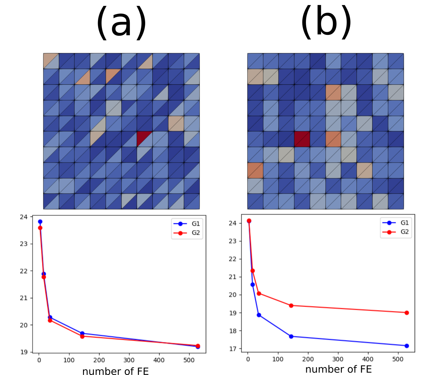
I'm solving this problem with the finite element method, and I'm comparing different strategies, for which I obtain contradictory results. In strategy A (see (a) on the picture below) I create a triangular mesh, and to each element, I assign certain properties (i.e., the elastic properties are element-wise constant through the system, as represented by the colormap in the picture of the mesh). Then I compute the $G_1$ and $G_2$ for many repetitions of the random elastic properties to have good statistics. I do the same for different mesh sizes (in the graph, the x-axis corresponds to the number of FE in the mesh). We observe that in fact, $G_1$ and $G_2$ are the same as expected.
In strategy B, I use the same triangular mesh but I set the values of the elastic properties considering pairs of triangular elements, in such a way that the spatial distribution of elastic properties resembles that of a quadrilateral mesh (see (b) on the picture). Surprisingly, $G_1$ and $G_2$ are no longer the same, and the difference does not decrease with system size.
I would like to point out that if I use homogeneous properties, as expected $G_1$ and $G_2$ are always the same, for both meshes and for any number of FE.
What's my final goal? I would like to solve exactly the same problem described above but with a quadrilateral mesh. With such a mesh, I find the same problem as with the triangular mesh (b). However, as proved by mesh (a), the problem doesn't seem to be intrinsic to the FE mesh itself. Therefore it might be possible to solve the problem correctly (i.e., without anisotropy) also on a quadrilateral mesh by tweaking something.
My question is: what's the origin of the macroscopic elastic anisotropy with the triangular mesh (b)? Why is it not there for the case (a)? Is there a way to palliate mesh dependency problems with quadrilateral meshes in FEM?

