0
$\begingroup$

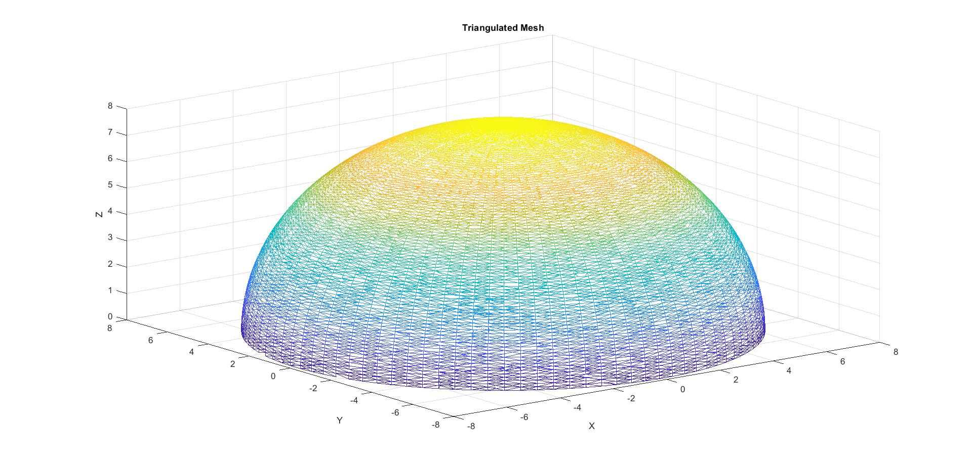
So I have this code where I am designing a hollow hemispherical shape and I want to create a 3D volume to input it into FEBio software.

Hollow hemisphere

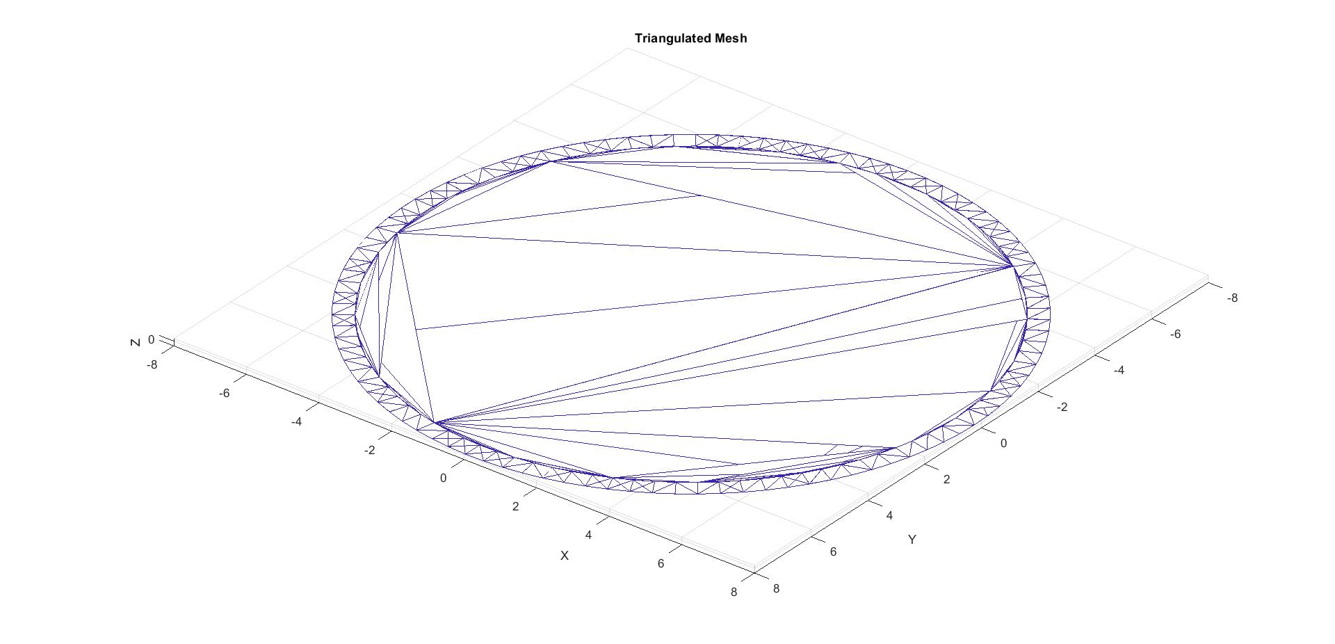
I am using delaunay triangulation for meshing. But the problem is when I rotate to see the bottom, I am seeing is that there are triangles there of this 3D model as shown below

unnecessary triangles

How do I remove these triangles that are connected at the bottom? I want to triangles only on the surface of the inner and outer hemispheres and between them.

clear
clc

outerRadius = 7.8; % Outer radius of the hemisphere
innerRadius = 7.3; % Inner radius of the hollow region

theta = linspace(0, pi/2, 100);
phi = linspace(0, 2*pi, 100);
[THETA, PHI] = meshgrid(theta, phi);

% Calculate the coordinates for the outer hemisphere
X_outer = outerRadius * cos(PHI) .* sin(THETA);
Y_outer = outerRadius * sin(PHI) .* sin(THETA);
Z_outer = outerRadius * cos(THETA);

% Calculate the coordinates for the inner hemisphere
X_inner = innerRadius * cos(PHI) .* sin(THETA);
Y_inner = innerRadius * sin(PHI) .* sin(THETA);
Z_inner = innerRadius * cos(THETA);

X = [X_outer(:); X_inner(:)];
Y = [Y_outer(:); Y_inner(:)];
Z = [Z_outer(:); Z_inner(:)];

% Combine the coordinates of the outer and inner hemispheres
points = [X, Y, Z];

% Remove duplicate points
[~, uniqueIndices, ~] = unique(points, 'rows', 'stable');
points = points(uniqueIndices, :);

% Separate the updated coordinates
X = points(:, 1);
Y = points(:, 2);
Z = points(:, 3);

% Generate the triangulated mesh
tri = delaunay(X, Y, Z);

% Plot the mesh
figure; set(gcf,'WindowState','maximized');
trimesh(tri, X, Y, Z);
xlabel('X'); ylabel('Y'); zlabel('Z');
title('Triangulated Mesh');
$\endgroup$
1
  • 1
    $\begingroup$ This seems to be a question best asked on the forum for this specific software. $\endgroup$ Commented Jun 29, 2023 at 16:37

2 Answers 2

3
$\begingroup$

Rather than relying on a delaunay triangulation, you could consider making a structured mesh directly, as you know how you are constructing the points and the ordering they follow. An icopshere would also be a good option for the geometry rater than the "UV sphere" you have got going here).

Tweaking the result for a predicable mesh like this is quite with boolean indexing, as long as one can formulate a condition for all the points, which is easy to brute force in this scenario, either by adding some sufficiently large/small eps. In this case, the halfway point between the inner and outer radius should suffice as the condition.

c1_radius = vecnorm(points(tri(:,1),:), 2, 2);
c2_radius = vecnorm(points(tri(:,2),:), 2, 2);
c3_radius = vecnorm(points(tri(:,3),:), 2, 2);
c4_radius = vecnorm(points(tri(:,4),:), 2, 2);
midRadius = (innerRadius + outerRadius)*0.5;
inside_elements = c1_radius < midRadius & c2_radius < midRadius & c3_radius < midRadius & c4_radius < midRadius;

tri(inside_elements,:) = [];  % delete them

Alternatives could be to check the triangle center

c = (points(tri(:,1),:) + points(tri(:,2),:) + points(tri(:,3),:) + points(tri(:,4),:))/4;
c_radius = vecnorm(c, 2, 2);
inside_elements = c_radius < innerRadius;

Note that the instructured nature of delaunay and the density of points here the top of the inside cap, I would be vary of the mesh not actually conforming to the shape you actually want; tetrahedral faces don't all have to end up on the inner surface, which you are assuming here.

$\endgroup$
2
$\begingroup$

I agree with Mikael's suggestion to use a structured mesh if you can get away with it. But there is a more fundamental reason why the Delaunay function from matlab isn't doing what you want and I think it's worth understanding.

The problem you're running into is that you've asked for the (unconstrained) Delaunay tetrahedralization of a point set $\{x_k\}$ in $\mathbb{R}^3$, when what you really have in mind is the constrained tetrahedralization of a surface mesh $S$, the vertices of which happen to be equal to $\{x_k\}$. This is a problem for two reasons. First, the unconstrained Delaunay mesh of a point set always contains the convex hull of that point set, so if the surface you have in mind is not convex then you'll get some extraneous external cells that you don't want. Second, there's no guarantee that the unconstrained Delaunay mesh is going to contain all the facets of the surface $S$ that you have in mind just by looking at the point set $\{x_k\}$. So what a constrained Delaunay meshing algorithm will do is:

  1. Compute the unconstrained Delaunay mesh of the $\{x_k\}$.
  2. Modify the topology of this unconstrained mesh so that it contains all of the facets of $S$ while preserving the Delaunay property.
  3. Remove any exterior cells from the mesh that lie outside the constraining surface $S$.

Constrained Delaunay meshing in 3D is a lot harder than in 2D. I don't know if matlab has a constrained Delaunay meshing function in 3D, so you could try looking at Tetgen instead. If you want to read more about this subject, this book is a fantastic resource.

$\endgroup$
2
  • 2
    $\begingroup$ Good points, i should have also mentioned that there is no guarantee that a Delaunay tetrahedron is going to be well shaped for finite element either; it can (and typically will) generate quite a few sliver elements (and delaunay isn't going to any sliver exudation) $\endgroup$ Commented Jul 1, 2023 at 20:34
  • 1
    $\begingroup$ To add to Mikael's point about slivers, there's literally an entire chapter in the book I referenced about getting rid of them. $\endgroup$ Commented Jul 1, 2023 at 21:14

Your Answer

By clicking “Post Your Answer”, you agree to our terms of service and acknowledge you have read our privacy policy.

Not the answer you're looking for? Browse other questions tagged or ask your own question.