I am a newbie in CFD and single/multiphase flow and transport in general. As part of my quest to learn, I am trying to model solute transport around a solid object in the center of a 2D domain. The governing equation is the advection-diffusion equation, given as:
where C is the concentration, v is the flow velocity, D is the diffusion coefficient. At a constant flow velocity, the above reduces to:
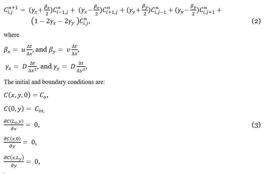
This is my code so far:
clc; clear; close all;

%%%%%%%%%% Specify inputs
CircleDiam = 40;        %in pixels
Co    = 0;          %initial conc. in the domain [mol/L]
Cin   = 0.01;       %conc. of injected fluid [mol/L]

Lx    = 0.1/100;        %Length of domain [m]
nx    = 200;        %spatial gridpoints in x
dx    = Lx/(nx-1);      %Length step size [m]
Ly    = 0.05/100;       %Width of domain [m]
ny    = 100;        %spatial gridpoints in y
dy    = Ly/(ny-1);      %Length step size [m]

T     = 5/(3600*24);    %Simulation time [days]
nt    = 8000;           %shifts
dt    = T/nt;       %Time step [days]

% Flow
u = 103.68;         %Velocity in x direction [m/day]
v = 0;              %Velocity in y direction [m/day]
De = 8.64e-04;      %Dispersion coeff. [m2/day]
betaX  = u*dt/dx;
betaY  = v*dt/dy;
gammaX = De*dt/(dx^2);
gammaY = De*dt/(dy^2);

%%%%%%%%%% Create image with solid object
radius  = CircleDiam/2;

% obtain full output grids from grid vectors
[Colgrids, Rowgrids] = meshgrid(1:nx, 1:ny);

% create a logical mask for the circle by specifying the center and diameter of the circle.
centerX = 0.5 + (nx/2);
centerY = 0.5 + (ny/2);

% obtain image from: ( (y-y0)^2 + (x-x0)^2 )  <= r^2, where (y0,x0) is the centre point of circle
SolidImg = (Rowgrids - centerY).^2 + (Colgrids - centerX).^2 <= radius.^2;

% change from logical to numeric labels. Also, transpose matrix to conform with the conc. matrix
P   = double(SolidImg');
%figure, imshow(~SolidImg, [], 'InitialMagnification','fit'); box on;

% Gridblocks
x = 0:dx:Lx;
y = 0:dy:Ly;
t = 0:dt:T;
[X,Y] = meshgrid(x, y);

%specify initial conditions
C        = zeros(nx, ny, nt+1);
C(:,:,1) =  Co;              %Initial condition

%iterate finite difference equations
for k = 1:nt
    for j = 2:ny-1
        for i = 2:nx-1

            if P(i,j)==1    %Solid pixels
                %C(i,j,k+1) = C(i,j,k);
                C(i,j,k+1) = 0;
            else
                C(i,j,k+1) = C(i-1,j,k)*(betaX/2+gammaX) + C(i+1,j,k)*(gammaX-betaX/2)...
                    + C(i,j-1,k)*(betaY/2+gammaY) + C(i,j+1,k)*(gammaY-betaY/2)...
                    + C(i,j,k)*(1-2*gammaX-2*gammaY);
            end

        end
    end

    % Insert boundary conditions
    C(:,1,k+1) = C(:,2,k+1);        % bottom bc
    C(:,end,k+1) = C(:,end-1,k+1);  % top bc
    C(1,:,k+1) = Cin;           % left bc
    C(end,:,k+1) = C(end-1,:,k+1);  % right bc

%     C_all = squeeze(C(:,:,k));
%     pcolor(C_all'); shading interp; colorbar; colormap(jet); hc = colorbar;
%     ylabel(hc,'Concentration [mol/L]');
%     caxis([0 max(max(max(C)))])
%     title( sprintf('Time = %f seconds', k) )
%     pause(0.001);
%
end
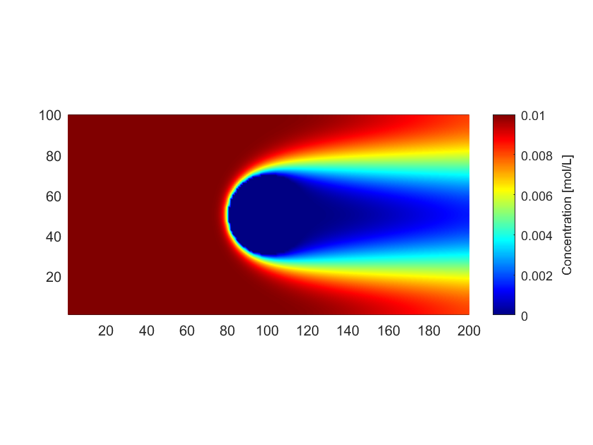
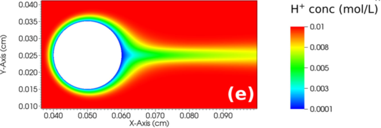
My result (see the first image) does not look like what I would expect. Ideally, I expect to see something like the above (second) image, and so I am wondering where I might be getting it wrong. I have assumed that both velocity and diffusion coefficient are zero at the solid boundary. Is there an additional boundary condition to be implemented at the solid boundary?
I would very much appreciate if someone can help me out here or point me in the right direction.
PS:
- The axes are the same in both image. The difference is that mine is in pixels while the other is in cm.
Thank you in anticipation.
EDIT:
- Previously, I had velocity in x = velocity in y. This is wrong because the flow is supposed to be coming from one edge only. I have now corrected this to be
velocity in x = +103.68 m/day, andvelocity in y = 0. - Previously, the boundary condition at the bottom edge was
C(:,2,k+1) = C(:,1,k+1);. It should have beenC(:,1,k+1) = C(:,2,k+1);. - The above changes means that I now have a much closer solution (see first image) to the problem than my previous version.


